


Device specification :
Board comes fully assembled!
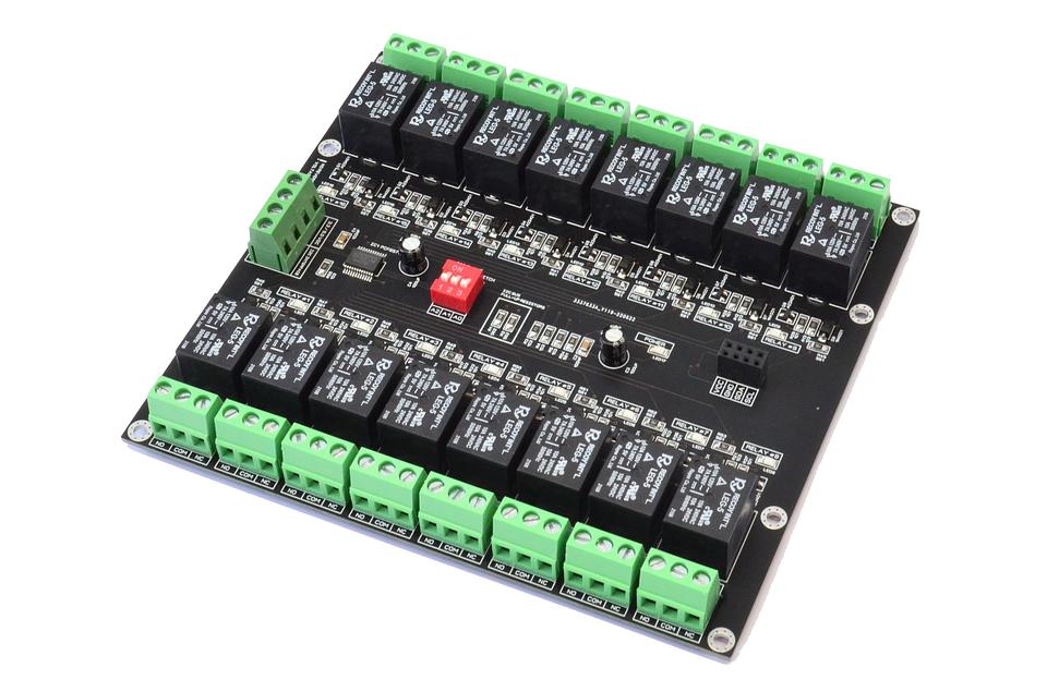
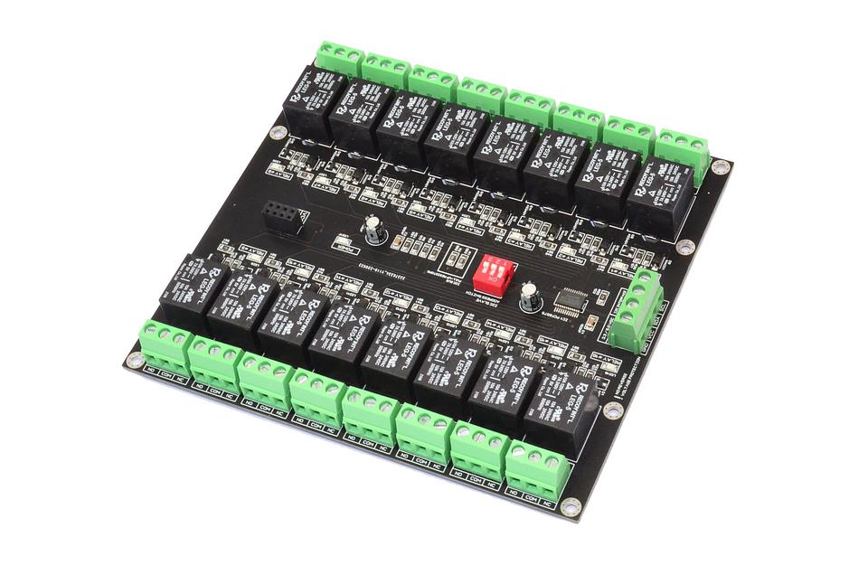
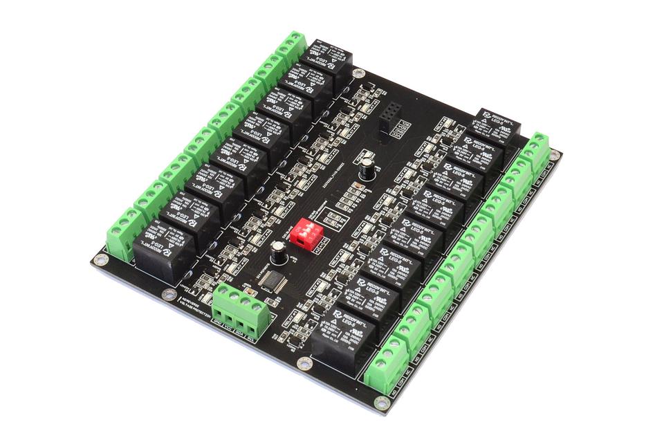
PCB board dimension 135mm x 150mm
Operation DC voltage – 3.3V and 5.0V
Maximum current @5.0V – 1500mA
Maximum current per relay – 5A...10A @ different voltages
LEDs indicators for each electromagnetic relay channel
Relays with SPDT switch contacts: Normally Open, Common, Normally Closed
Relay contact resistance 100 milliohms max. ( initial value )
Relay insulation resistance 100 MOhm min. (DC 500V)
Relay operation time 8 ms max
Relay release time 5ms max
Relay dielectric strength 750 VAC, 50/60Hz between contact
Relay dielectric strength 1,500 VAC, 50/60Hz between all elements
Relay expected life Mechanical - 10,000,000 operations min.
Relay expected life Electrical - 100,000 operations min. at rated load
Working temperature range - 25 C ~ + 80 C
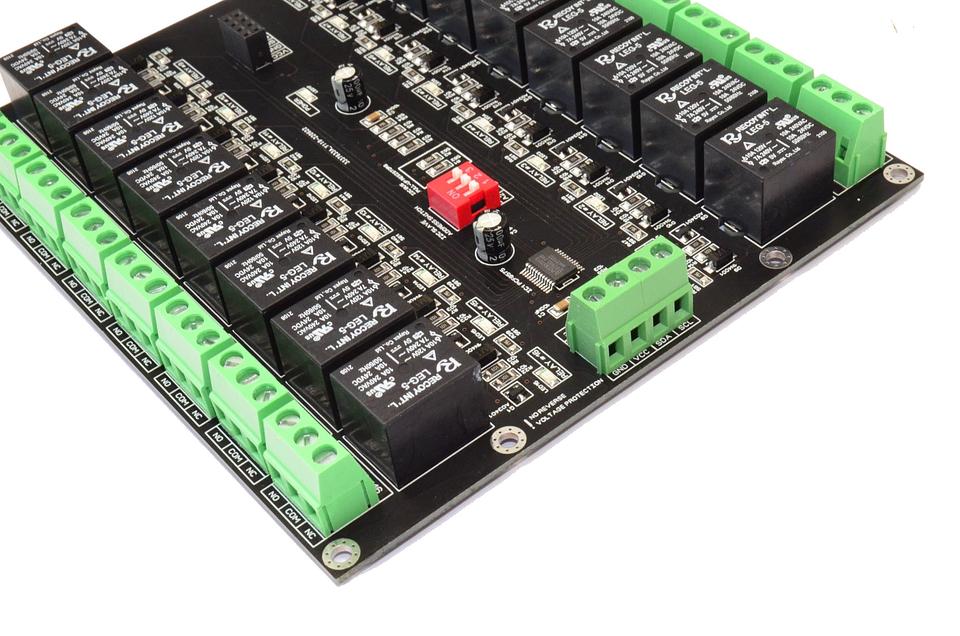
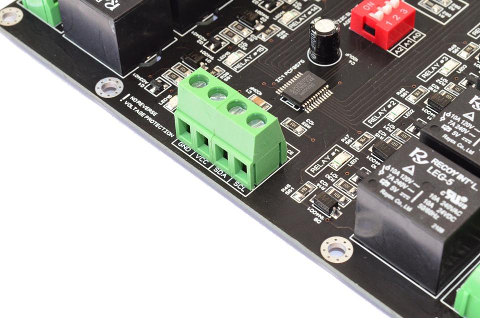
Each board can be assigned an I2C address between 0x20...0x27 by the DIP switch
The module contains an PCF8575 chip
The logic power supply voltage should match the voltage levels on the I2C bus. The SDA and SCL lines are pulled up to VDD with 5.6k resistors on the relay module.
Up to 8 boards can be connected to each I2C bus. 8 x 16 = 128 relays can be controlled via 4 wires!
Depending on the relay stock available, the relay manufacturer may differ
HOME ASSISTANT:

Arduino sample codes:
Arduino sample code for 0x27 slave address, *ino - download here
Arduino sample code for 0x27 slave address, *txt - watch here
Multiboards code, *txt - watch here
Arduino PCF8575 library *zip - download here
Shipping information:
Worldwide shipping with/without tracking number.
Please track your tracking number at 17track.net or track-trace.com.
Dispatching next business day.
Estimated delivery time to Europe 14-28 business days, others countries up to 30 days.
For express shipping please contact before order
Free contact me, if you have any question !
Links to code and documentation
Documentation (drive.google.com)
Design Files (drive.google.com)