

The Challenger RP2040 LoRa
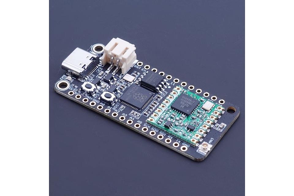
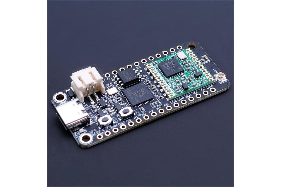
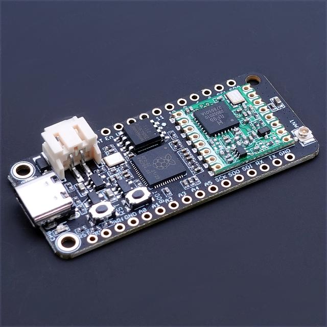
The Challenger RP2040 LoRa is a small micro controller board with a LoRa modem module on board, in the popular Adafruit Feather form factor. It is based on an RP2040 micro controller chip from the Raspberry Pi foundation which is a dual core Cortex M0 that can run on a clock up to 133MHz.
The RP2040 is paired with a 8MByte high speed flash capable of supplying data up to the max speed. The flash memory can be used both to store instructions for the micro controller as well as data in a file system and having a file system available makes it easy to store data in a structured and easy to program approach.
The device can be powered from a Lithium Polymer battery connected through a standard 2.0mm connector on the side of the board. An internal battery charging circuit allows you to charge your battery safely and quickly. The device is shipped with a programming resistor that sets the charging current to ~450mA. this resistor can be exchanged by the user to either increase or decrease the charging current, depending on the battery that is being used.
The LoRa part of this board is based on the Hope RF module RFM95W which is a complete solution for implementing a LoRa radio on a very limited space.
The RFM95W is connected to the micro controller using SPI channel 1 (SPI1) and a few GPIO signals to handle signaling from the modem circuit. Besides the modem module there is basically only one additional U.FL connector that forms the modem functionality. Simply hook your external antenna to this connector and you are ready to go.
Short introduction to the board
PCB
The board is based on a popular form factor called “Feather” which is created and maintained by an American company called Adafruit. The entire specification for the Feather format is available here. The size of the PCB for the module is 50.80mm x 22.86mm but the entire module is a little bit bigger as the Type C USB connector protrudes about 1 mm outside the board.
Antenna On the opposite end from the USB connector the you will find the antenna connector. This is a U.FL (IPEX) connector that works very well within the frequency band of LoRa. When mounting the antenna into or onto any enclosure you should make sure to keep stuff like cables and/or walls from the enclosure away from the antenna as much as possible. Anything mounted in the vicinity of the antenna will affect its performance.
Headers
On each of the longer sides of the PCB there are holes intended for soldering pin header connectors. If you don’t want to use connectors for some reason you can also solder a wire directly into the hole, making a permanent connection to your external device. If you go this way please make sure that the wires are fixed in place, otherwise vibrations can cause the wire to brake at the soldering point.
LED’s
On each side of the USB connector there is a small indicator LED placed. The LED which is marked CHG is the charge control indicator. This red LED will shine whenever the connected battery is being charged, and when the battery is fully charged the LED will turn off again. If you haven’t connected a battery to the board this LED will not come on at all.
On the other side of the USB connector there is a user programmable green LED. This LED is connected to pin D15 and can easily be controlled by the user program. Hardware details
Pins

The on board micro controller (RP2040) have a number of communication channels that have been routed out to the side (header connector) connectors.
- UART – One UART channel have been routed to the header pins (RX, TX). The micro controller have 2 UARTs but on this board only the first UART is used.
- SPI – One SPI channel have been routed to the header pins (SCK, SDO, SDI) and the other SPI channel is connected to the RFM95W LoRa module.
- I2C – One I2C channel have been routed to the header pins (SCL, SDA).
- Analog pins – The micro controller have 4 analog input pins that all are available on the header pins (A0-A3).
- PWM – All pins can be used for PWM.
The pin chart below shows the placement of all pins and their respective functions. When working in an Arduino environment (or Platform IO) use the blue pins when writing your code and when working with CircuitPython use the orange marked pin assignments. Power
The board can be powered from multiple sources. The most obvious way to run the board is by plugging it in to a USB cable and attach it to your computer. In this mode you can write software and test the board with all its functionality.
There is also a third way to supply the board. This way is more invasive and will disable the onboard 3.3V power regulator.
You will have to pull the EN header pin low and then supply your own 3.3V voltage on the 3.3V header pin. Please note that when disabling the onboard power regulator you will have to supply the 3.3V also when running the system on battery power. Battery
As described earlier the board can be powered from a LiPo battery. The battery can be connected using a standard 2.0mm JST connector through the battery connector on the right side of the board or ff the battery is an integral part of the system that you are designing it is possible to connect the battery through the BAT pin instead.
Switching between the battery voltage and the applied USB voltage or external 5V is done seamlessly by the on board circuitry.
Charging of the battery is done by either connecting a USB cable or by connecting a 5V power source to the header pin marked USB on the board. If you do this make sure you connect your voltage through a 1A schottky diode to avoid any excessive current draw in the system when the two levels are slightly different.
Please note that providing external charger circuitry could destroy the internal charger on the Challenger board. Connection between MCU and the RFM95W LoRa modem.
The board uses the second SPI channel (SPI1) of the MCU to connect to the RFM95W module as well as a few GPIO pins to communicate with the module. The pins used are as follows.
- GPIO9 – GPIO12 is configured as SPI bus 1 (SPI1) and is connected to the SPI bus
- GPIO9 – LORA_CS
- GPIO10 – LORA_SCK
- GPIO11 – LORA_MOSI
- GPIO12 – LORA_MISO
- GPIO13 is connected to the reset input of the RFM95W.
- GPIO14, GPIO15 and GPIO18 is connected to DIO0 – DIO2 respectively of the RFM95W.
- GPIO24 is connected to the general purpose LED.
Links to code and documentation
Shipping policy
We normally pack items on Mondays and leave them at the post office on Tuesdays. Orders received after 12:00 (CET) on Monday will be shipped the following week.
