Challenger RP2040 WiFi
Sold by ILabs Electronics
$15.47
No tax for United States [change]
So what is this thing
The Challenger RP2040 WiFi is an Arduino/Micropython compatible Adafruit Feather format micro controller board based on the Raspberry Pico chip.
When we designed this board we took our existing Challenger M0 WiFi board and replaced the SAMD21 micro controller with the much more powerful dual core RP2040 Cortex-M0 device. The RP2040 have two Cortex-M0 CPU cores clocked at 133Mhz and 264Kbyte SRAM integrated. On our board we decided to put a 8MByte flash memory for your programs and file storage.
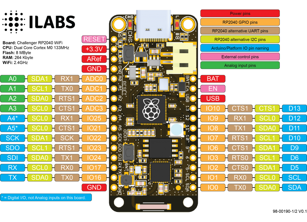
Pin assignments

WiFi
Just like the Challenger M0 WiFi it has a ESP8285 WiFi chip. For those of you that is unfamiliar with this device, it is basically an ESP8266 device with an integrated 1MByte of flash memory. This allows us to have an AT command interpreter inside this chip that the main controller can talk to and connect to you local WiFi network. The communications channel between the two devices is an unused UART on the main controller and the standard UART on the ESP8285. As simple as it can be.
The ESP8285 chip comes pre-flashed with Espressif’s AT command interpreter stored in the internal 1MByte of the ESP8285. This interpreter support most of the operating and sleep modes of the standard ESP8266 framework which makes it easy to work with. Talking to the device is as easy as opening the second serial port (Serial2), resetting the ESP8285 and start listening for events and sending commands.
We recommend using the WiFiEspAT library when writing networked applications. It works very well and comes with extensive examples for different usages. Installing this library is as easy as 1-2-3, simply press <ctrl-shift+I> in the Arduino IDE and search for "wifiespat". Install the library and off you go. Check here for more details on how to use the library with the Challenger boards.
You can of course replace the default AT interpreter with your own software if it doesn't meet your requirements.
Buttons
There are two buttons on the board. The button closest to the USB connector is the reset button. Use it whenever you need to reset the unit. It has exactly the same functionality as the RESET pin. Then there is the boot button towards the rear end of the board. This button must be used in conjunction with the reset button to reset the RP2040 into UF2 mode. Press the BOOT button, then the RESET button for a short moment. Then release the RESET button (while still pressing the BOOT button) and shortly after that release the BOOT button. This will place the board in UF2 mode and show up in the computer as a mass storage device.
USB Type C
In the recent years we have noticed that we are seeing more and more USB Type C cable laying around the lab due to the fact that all new phones and accessories use them. As of yet we haven’t seen any shortage of micro USB cables but we are not getting any new ones any more and old ones do break occasionally. So we decided to go for a USB Type C connector for this board. A bonus of this is that they are quite bit more durable and you don’t have to fiddle with the cable before plugging it in.
Using the Arduino environment
We’ve teamed up with Earle F. Philhower over at his Github page to provide Arduino support for our Raspberry Pi Pico based boards. All instructions on how to install the board support packaged as well as multiple examples on how to use the Raspberry Pi Pico processor.
MicroPython
The Challenger 2040 WiFi board is fully compatible with both the micropython package found at the Raspberry Pi site as well as Adafruits CircuitPython. Instruction are available on how to install the python interpreter of your choice is available on respective web site.
Technical details
Main Processor
- Raspberry Pi Pico Dual Core Cortex-M0 @ 133MHz
- 8 MByte FLASH Memory.
- 264 KByte SRAM Memory.
- 1 Hardware I2C channel.
- 1 Hardware SPI channel.
- 1 Hardware UART for the user (Serial1).
- 1 Hardware UART connected to the network processor (Serial2 @ 1Mbit/s)
- 12 Bit ADC.
Network Processor
- ESP8285 with internal 1MByte FLASH Memory
- WiFi (2.4GHz)
- Espressif AT interpreter
- Communicates at 921600 bits/s
Board functions
- Neopixel LED
- LiPo charger circuit with 250mA charging current
- Standard LiPo battery connector
- USB Type C connector
Links to code and documentation
Shipping policy
We normally pack items on Mondays and leave them at the post office on Tuesdays. Orders received after 12:00 (CET) on Monday will be shipped the following week.


