do_not_disturb This store is temporarily paused.
.png)
.png)

A 18650 LiPo Battery Manager with Fuel Gauge and Dual Rail Power Supply
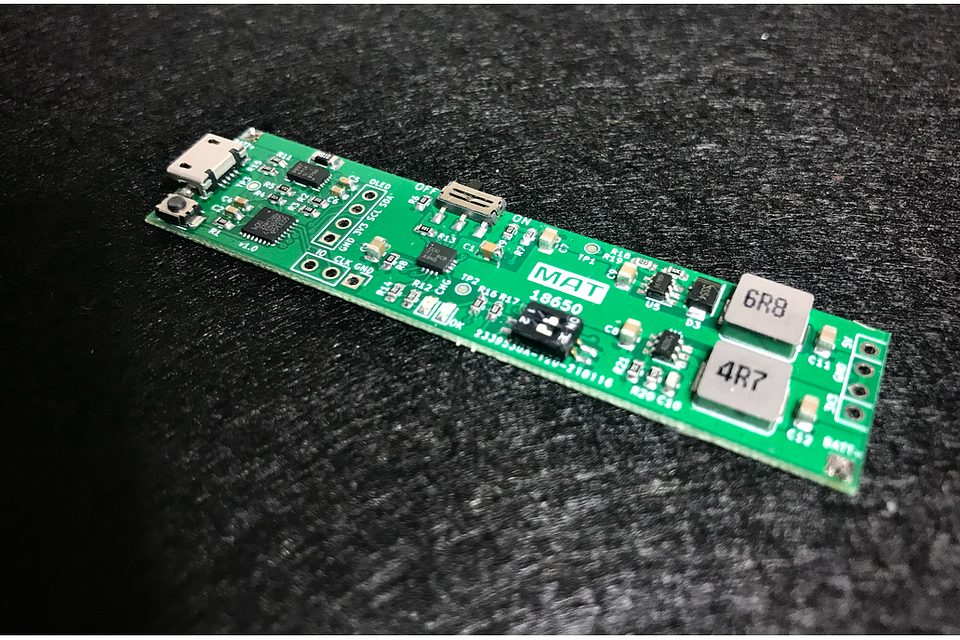
All-in-one single-cell LiPo battery manager. It's a battery charger, battery monitor and a dual-rail power supply (3.3V and 5V). You can use it with any kind of single-cell LiPo battery, but it's designed with a form factor to be attached on the back of a 18650 battery box, so you can use it as a Power Bank for your projects.
Battery Charger
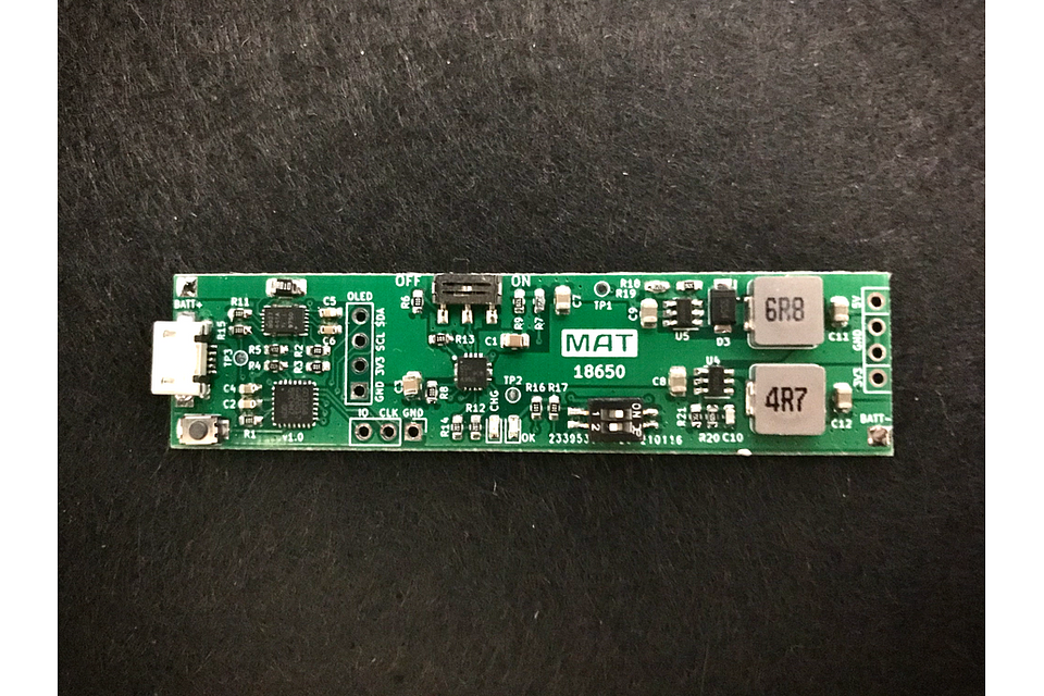
Battery charging is managed by a bq24075 IC from Texas Instruments, with the following features:
- Maximum charge current configurable through a DIP switch: 1A, 500mA, 100mA
- Reverse current, Short-circuit and thermal protection.
- Dynamic Power Path Management (DPPM): Output is active whenever a source is connected to USB or BAT, guaranteeing power to your project even if the battery has died. The input current from USB is shared and balanced between charging the battery and powering the system load at OUT.
- Battery Supplement Mode: During the charge process, when the output current exceeds the limit configured by DIP switch (1A, 500mA or 100mA), the battery supplements the system load without any regulation, so you can always get the max current provided by your battery.
You can disable the system with the toggle switch. When off, the battery will be disconnected to system output and all charge will be disabled. When ON, two LEDs indicates a valid input charge detection (ON) and the battery charging process (CHG).
Maximum charge current can be selected through the DIP switch, with the following configurations.
| PIN 1 | PIN 2 | Max. Current |
|---|---|---|
| Down | Down | Standby (USB suspend mode) |
| Up | Down | 1A. |
| Down | Up | 500 mA. USB500 mode |
| Up | Up | 100 mA. USB100 mode |
The battery is charged in three phases:
- Conditioning pre-charge, charging at 100mA until battery raises 3V.
- Constant current fast charge, with charge current configured via DIP Switch until the battery reaches 4.2V
- Constant Voltage Tapering, holding a constant voltage while current tapers off as the battery approaches full charge.
The bq24075 contain a thermal regulation loop that monitors the die temperature. If the temperature exceeds 125ºC, the device automatically reduces the charging current to prevent the die temperature from increasing further. Also provides thermal shutdown protection, so if the temperature increases to 155ºC the charge process is fully disabled, but the battery will remain active to powers the load.
NOTE: Keep in mind that these features monitor the die temperature of the IC due to power dissipation, battery algorithm and its LDO output. This is not synonymous with ambient temperature.
Fuel Gauge Monitor
The board features a BQ27441-G1A fuel gauge from Texas Instruments, based on Impedance Track™ Technology, that accurately predicts the battery capacity and other operational characteristics of a single Li-based rechargeable cell. The fuel gauge measures the charging and discharging of the battery by monitoring the voltage across a small-value sense resistor (10mΩ). When a cell is attached to the fuel gauge, cell impedance is computed based on cell current, cell open-circuit voltage (OCV), and cell voltage under loading conditions.
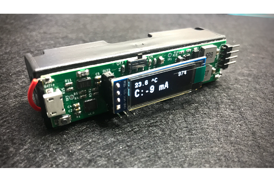
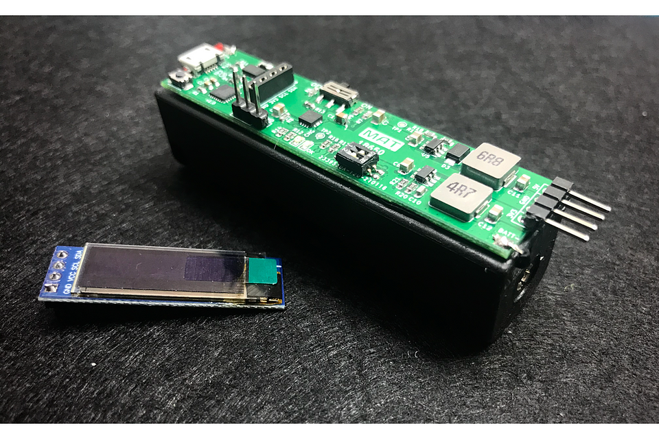
The IC is interrogated by a STM32G031G8U6 microcontroller, and all information is displayed in a 0.91" OLED Display (optional purchase). This is the information displayed on the screen:
- State Of Charge (in %, always visible)
- Temperature (in ºC, always visible)
- Average Current (C, in mA)
- Average Power (P, in mW)
- Remaining Capacity (R.C., in mA)
- Battery Voltage (V, in mV)
- Design Capacity (D.C., in mA)
- Full-Charge Capacity (F.C., in mA)
- State Of Health (HLTH, in %)
You can cycle through this information by pressing the switch button.
Once the battery inserted, the information displayed is based on the IC algorithm with the default register data. As we make charge and discharge iterations, these registers will be adjusted to show more accurate values, but keep in mind that this information will be reset to default values once the battery is removed.
For a proper operation, some of these registers must be configured based on the specs of your battery: Design Capacity (the mAh value of the battery), Design Energy, Termination Voltage (value that represents 0%) and Taper Rate. The microcontroller detects when the battery is removed and setup these values again once inserted. You can use the provided source code (link) to easily adjusts these parameters and upload the firmware via the onboard SWD port.
PLEASE NOTE: Select the design capacity of your battery when placing an order. If you don't find the correct value, send me a message and I'll add it to the list.
Dual Rail Power Supply
The board provides the following power rails:
5V Power Rail
- High-efficiency step-up converter: up to 97%.
- 2A output current
- Fixed switching frequency of 1.2MHz
- Automatic shifting to pulse frequency modulation at light loads.
- Under-voltage lockout, current limiting (4A internal switch), thermal overload protection and a soft-start to ensure a small inrush current.
3.3V Power Rail:
- Synchronous step-down converter.
- 2A output current
- High efficiency of 98% (0.5A load current).
- Constant frequency operation of 1.5MHz
- Pulse Frequency Modulation mode for high efficiency in light load.
- Short circuit protection, thermal fault protection, inrush current limit (4A) and soft start.
This rail is also used to power the MCU and the display port.
Ordering Options
When placing an order you can choose between these options:
- PCB: Fully assembled PCB, without battery case nor display.
- Full kit: with this option the PCB is fixed on the back of a battery case with RTV silicone and includes a 0.91" TFT OLED (you can choose between blue and white display color). Oled display and port uses low profile pins (female on board, header on LCD), so you can remove the display at any time.
Battery not included.
Links to code and documentation
Shipping policy
All items are shipped via Certified mail with tracking number, and delivered under signature to the recipient's address.
Typical delivery times are 2-4 business days to Europe, depending on location.
Please note that orders placed on weekends will be shipped from Monday